720079201 (6/09)

Part No. 720056901

© Baxi Heating UK Ltd 2009
Page 1
1.0 Introduction
2.0 Technical Data
3.0 Important Information &
Operation
4.0 Installation
5.0 General Notes
The 'GasSaver' is approved for use with the following boiler models:-
Natural Gas
Baxi Duo-tec Combi 24 HE A
G.C.No 47 075 35
Baxi Duo-tec Combi 28 HE A
G.C.No 47 075 36
Baxi Duo-tec Combi 33 HE A
G.C.No 47 075 37
Baxi Duo-tec Combi 40 HE A
G.C.No 47 075 38
Baxi Platinum Combi 24 HE A
G.C.No 47 075 31
Baxi Platinum Combi 28 HE A
G.C.No 47 075 32
Baxi Platinum Combi 33 HE A
G.C.No 47 075 33
Baxi Platinum Combi 40 HE A
G.C.No 47 075 34
Potterton Promax Combi 24 HE Plus A
G.C.No 47 393 21
Potterton Promax Combi 28 HE Plus A
G.C.No 47 393 22
Potterton Promax Combi 33 HE Plus A
G.C.No 47 393 23
Potterton Gold Combi 24 HE A
G.C.No 47 393 18
Potterton Gold Combi 28 HE A
G.C.No 47 393 19
Potterton Gold Combi 33 HE A
G.C.No 47 393 20
© Baxi Heating UK Ltd 2009 All rights reserved. No part of this publication may be reproduced or transmitted in any form or by any means, or stored in any retrieval system of any nature (including in any database), in each case whether electronic, mechanical, recording or otherwise, without the prior written permission of the copyright owner, except for permitted fair dealing under Copyrights, Designs and Patents Act 1988.
Applications for the copyright use of any part of this publication should be made, giving details of the proposed use, to the following address:
The Company Secretary,
Baxi Heating UK Ltd,
The Wyvern Business Park,
Stanier Way,
Derby,
DE21 6BF.
Full acknowledgement of author and source must be given.
WARNING: Any person who does any unauthorised act in relation to a copyright work may be liable to criminal prosecution and civil claims for damages.

page 2
2. The Multifit pre-heat incoming cold mains water, thus reducing gas consumption during the production of Domestic Hot Water.
3. The ‘GasSaver’ licence from Zenex Technologies Limited.
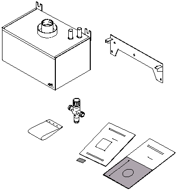
The pack contains:-
Support Bracket
Wall Fixing Screws
Blending Valve
Template
Literature
SAPLabel

2. Further flue lengths or bends may be used, but a loss in output of 1% is incurred for every additional metre (or equivalent).24 models - 5 metres
28 models - 5 metres
33 models - 3 metres
40 models - 1 metre
3. The 60/100 concentric horizontal or vertical flue system (Flue Group A) approved for the boilers listed in 1.1.3 must be used.
NOTE: Maximum equivalent flue length remains at 10 metres
The following items are available as an accessory:-
Expansion Vessel &Check Valve Kit 720066401
Stand Off Fittings Kit 720079701
page 3
|
DHW Circuit Pressures |
bar |
|||
|
Max Inlet- |
5* |
|||
|
Min Operating - |
0.2 |
|||
| *if required fit a pressure reducing device to achieve this | ||||
|
DHW Circuit Flow Rates |
l/min |
|||
|
Max Flow Rate- |
20 |
|||
|
Min Flow Rate-
|
2.5 |
|||
|
Connections |
stainless steel |
|||
| Cold Water Mains Inlet- | 15mm | |||
|
Pre-heated Mains Outlet- |
15mm |
|||
|
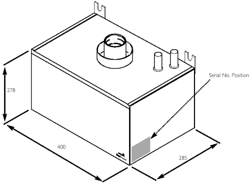
Dimensions (Fig. 1) |
mm |
|||
|
Casing Height- |
278mm |
|||
|
Casing Width- |
400mm |
|||
|
Casing Depth- |
285mm |
|||
|
Weights |
kg |
|||
|
Packaged Boiler Carton- |
18.5 |
|||
|
Installation Lift Weight- |
15.6 |
|||
|
Weight -Full- |
24 |
|||
|
Clearances |
mm |
|||
|
Above Casing |
- 200 mm Min |
|||
|
Below Casing |
- 80 mm |
|||
|
Front |
- 450 mm Min (For Inspection) |
|||
|
Front |
- 5 mm Min (In Operation) |
|||
|
L.H. Side |
- 25 mm |
|||
|
R.H. Side |
- 25 mm |
|||
|
Blending Valve |
||||
|
Connections- |
15mm |
|||
|
Setting Temperature- |
300C | |||
|
General |
||||
|
DHW H/Exch.- |
Stainless Steel |
|||
|
Store &Flue Connection- |
Stainless Steel |
|||
|
Casing- |
White Paint - Steel |
|||
|
Condensate Store Capacity- |
5.5 litres |
|||
|
H/Exch Coil Capacit- |
2.7 litres |
|||

page 4
2. The current Gas Safety (Installation & Use) Regulations must be observed, along with all relevant Building Regulations/Standards, Water Regulations/Standards and the B.S. Codes of Practice listed in the boiler instructions.
3. A special wall fixing bracket is supplied to mount the ‘GasSaver’ on - this must be used
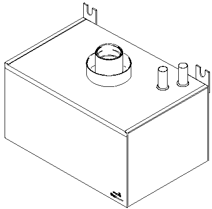
4. The ‘GasSaver’ is in effect part of the flue system and should be considered as such.
5. When using the boiler stand off bracket kit it is also necessary to use the fittings kit 720079701.
6. These instructions must be read in conjunction with those supplied with the boiler.

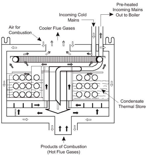
Fig. 2
2. The diagram opposite shows how the heat is transferred from the flue gases into the mains cold water.
3. A gas-to-water heat exchanger extracts heat from the discharged products of combustion (hot flue gases). This heat is used to pre-heat the incoming cold mains before it is heated for domestic hot water purposes.
4. During the transfer of heat from the flue gases further condensation occurs, allowing latent heat to be captured. This condensate is utilised to form a thermal store within the used in the pre-heat process.
5. Additionally, as the flue gases leaving the GasSaver contain considerably less moisture, the amount of pluming is reduced.
page 5
2. Align the ‘GasSaver’ and mark the positions of the flue and upper fixings.
3. Position the above the boiler wall plate. Align the smaller flange against the wall plate with the larger flange and two side tabs uppermost (Fig. 4). Mark the most suitable fixing holes.
4. Drill & plug the upper and bracket fixings. Make the hole for the flue.
5. Continue to install the boiler on the wall plate (Fig. 5). Secure the mounting bracket with suitable screws (Fig. 6).
6. The ‘GasSaver’ connection on the underside of the boiler flue adaptor, taking care to not displace the seals.
7. Whilst supporting the with the screws and washers provided using the upper fixing brackets (Fig. 7).
8. To ensure correct and efficient operation the must now be primed (Fig. 8) by pouring 6 litres of clean cold water into the central spigot. Do not allow any water to spill into the air chamber.
9. The flue system can now be installed (Fig. 9) and commissioning completed. The flue adaptor on top of the ‘GasSaver’ is the same as that on the boiler
Fig. 3
Fig. 4
Fig. 5
Fig. 6
Fig. 7
Fig. 8
Fig. 9
page 6
NOTE: WRAS certification requires an approved single check valve or some other no less effective backflow prevention device to be fitted at the point of connection between the supply and the device.
2. The blending valve should be set so that mains water is supplied to the boiler at 30° C. Set it to minimum and check the temperature, adjusting if necessary.
3. Certain circumstances require the installation of an expansion vessel on the mains inlet - see Section 6.0 of the boiler Installation & Servicing Instructions.
4. Apply the SAP label to the boiler door and (Fig. 12).
5. The ‘GasSaver’ will operate at full effectiveness after approximately 24 hours operation.
2. It is recommended that every time the boiler is serviced the ‘GasSaver’ is subjected to a visual inspection of its’ overall condition.
Fig. 10
Fig. 11
Fig. 12
page 7
All descriptions and illustrations provided in this leaflet have been carefully prepared but we reserve the right to make changes and improvements in our products which may affect the accuracy of the information contained in this leaflet. All goods are sold subject to our standard Conditions of Sale which are available on request.
MULTIFIT
A Registered Trademark of Baxi Heating UK Ltd (3879156)
Brooks House, Coventry Road, Warwick. CV34 4LL
Technical Enquiries 0844 871 1555
Websites:- www.baxiheating.co.uk
![]()
720079201 (6/09)
page 8